I made two kinds of boards for my Eurorack case: compact supply cards, designed with low noise in mind, and long bus boards for power distribution.
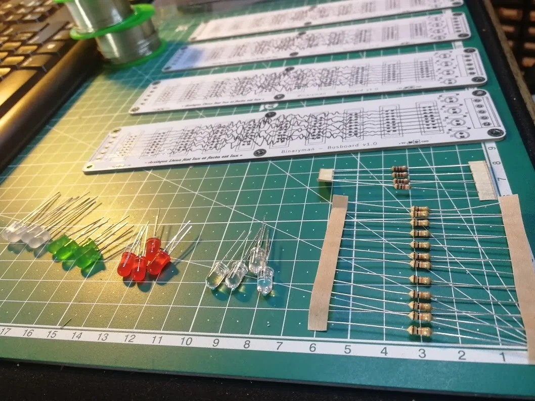
Bus boards and components prepared for soldering.
Supply cards
The supply cards use through-hole components, screw terminals, capacitors, heatsinks, and LED indicators. Connector labels remain visible on the silkscreen after assembly.
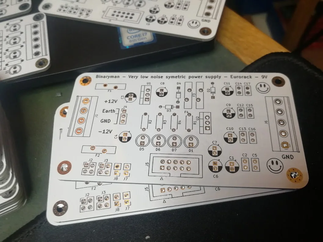
Bare supply cards before assembly.
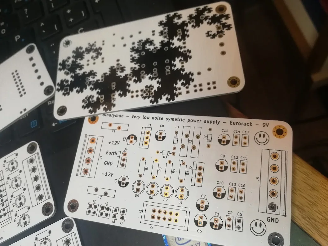
Component placement on the front; fractal artwork on the reverse.
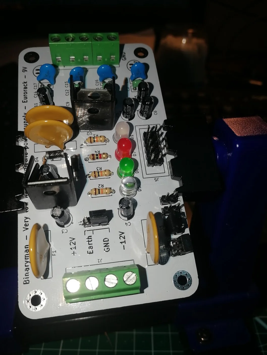
A populated supply card on the workbench.
Distribution buses
The long PCBs carry repeated power connectors, screw terminals, and indicator LEDs. Keeping distribution on separate boards allows the connectors to be placed along the case, close to the modules.
I also used the silkscreen for artwork: waveforms along the bus boards and fractal patterns on the supply cards.
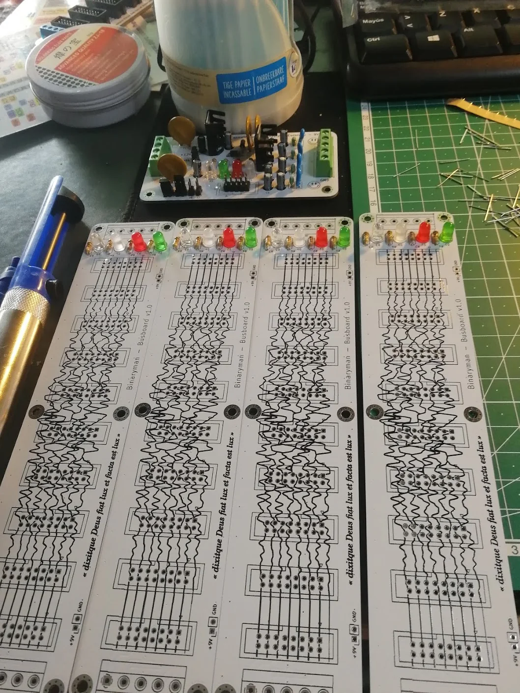
Four bus boards during assembly, with a supply card behind them.
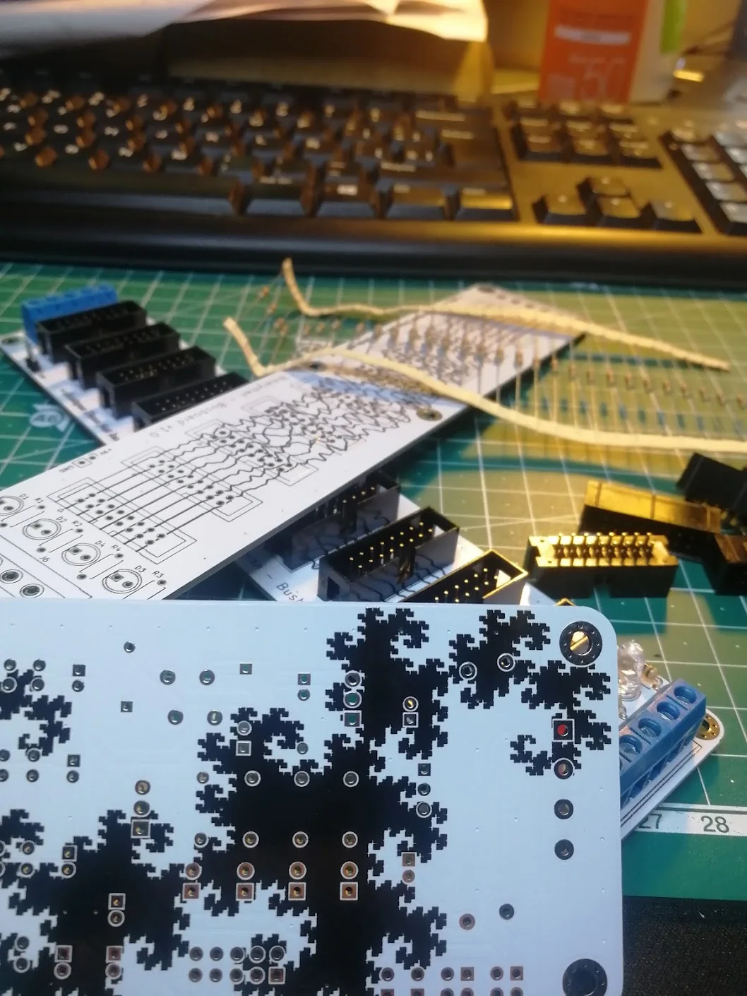
Power connectors and the PCB artwork.
This build is part of Binary Instruments, my Eurorack hardware work. Related designs are collected in the Binary Instruments repository.
The acacia case build from May 2021 shows these boards installed and wired, with a retrospective note on the bus-voltage error.